Three Essential CAM Toolpaths in Fusion 360
When you’re just starting your CNC journey, programming CAM (computer-aided manufacturing) in Autodesk Fusion 360 can be overwhelming. There are so many options to choose from—and even more boxes to check off—that it’s sometimes difficult to know where to begin. Not to worry! In this how-to, we show you how to program facing, adaptive, and contour toolpaths in Fusion 360.
While it can seem daunting, Fusion 360 is an amazing tool. It’s a cloud-connected system that allows you to model your design via CAD (computer-aided design) and program your CAM in one place, across multiple devices. Fusion 360 also allows you to share your design files with other users in the community. And the best part is that the G-code it generates can be imported right into our Bantam Tools Desktop Milling Machine Software.
For this how-to, we’re using machining wax, a prototyping material we often use to test our designs and, more importantly, our CAM toolpaths. We’ll be using our machining wax bottle opener as an example, but you can follow the steps using your own design files too.

To start programming your CAM, click on the Design dropdown menu in the top left corner and scroll down to Manufacture. CAM can be broken up into two parts: stock setup and toolpaths.

Part 1: Set Up Your Stock
At a minimum, you’ll need to specify three things to set up your stock:
Stock size
Model orientation in the stock
Work coordinate system (WCS)
Stock size: Under Manufacturing, click Setup > New Setup. Notice how there are three tabs in the window that appears on your screen. Click the Stock tab and make sure that “Fixed size box” is selected for the Mode. This will allow you to adjust the dimensions of the stock.

Note: When choosing your stock, think about how much material is going to be cut away to machine your model. Naturally, the less material that needs to be cleared, the more efficient your toolpaths.
Model orientation: You may have noticed that your model is floating in the center of the stock. You’ll want to orient the model within the stock to optimize your mill job. In the Stock tab, click Model Position under Height, select Offset from Bottom, and enter 0”. This will make the bottom of your stock and model the same. Depending on your design, you may want to offset the width and depth as well.
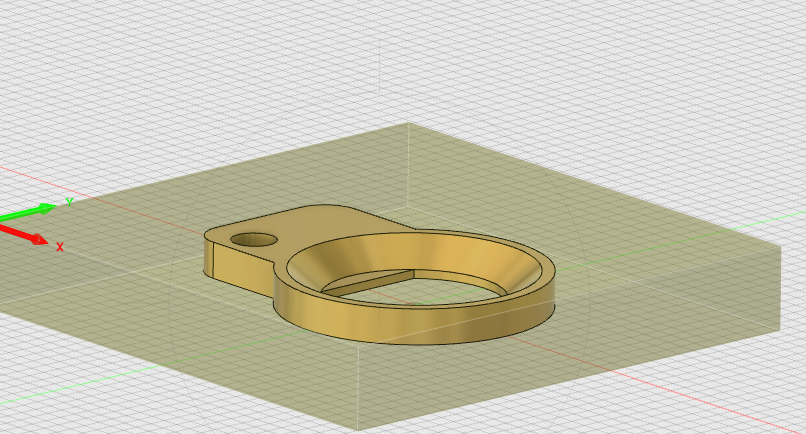
Before you orient your model in Fusion 360.
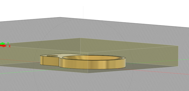
After you orientate your model in Fusion 360.
WCS: Specify the coordinate system that the toolpaths will use to machine your design. For this bottle opener project (and all projects on the Desktop PCB Milling Machine) we default to selecting the topside, front left corner of the stock.

When you’ve gone through each of these steps, click OK.
Part 2: Program Your Toolpaths
After you’ve set up your stock, you can start programming the three essential toolpaths: facing, adaptive, and contour. If you haven’t done so already, import our tool library into Fusion 360.
For each toolpath, you’ll need to enter five important cutting parameters: spindle speed, cutting feedrate, plunge rate, stepover, and stepdown. To take the guesswork out of what to enter for each of these values, check out these material speeds and feeds reference charts:
Facing toolpath: This toolpath removes material from the top of your stock down to the top of your model. To begin programming this toolpath, click the 2D dropdown menu and select Face. Under the Tool tab, choose your tool (we used a ⅛” flat end mill for our bottle opener), and then enter your:
Spindle speed
Feed rate
Plunge depth
Next, under the Passes tab, enter:
Stepover
Maximum stepdown

When you’re done, click OK.
Adaptive toolpath: This toolpath clears the bulk of your material in the most efficient way possible using a high-speed machining (HSM) strategy that avoids sharp 90º turns. To generate this pass, click 3D > Adaptive Clearing. Generally, we like to use the same tooling and speeds and feeds for the adaptive pass that we used for the facing pass. Again, you’ll choose your tooling and then enter your spindle speed, feedrate, and plunge depth under the Tool tab.
When you go to input your stepover and stepdown, you’ll notice the options in the Passes tab look a little different. For adaptive toolpaths, the Optimal Load is essentially the stepover, and Maximum Roughing Stepdown is the stepdown.
Rather than machine away all the material, program this toolpath to clear only what you need to optimize your milling operation—remember, efficiency! Click the Geometry tab and then create a machining boundary. We input a 0.25” boundary around the outer contour of our bottle opener.

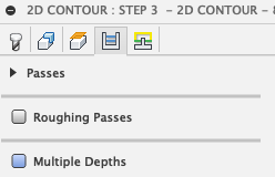
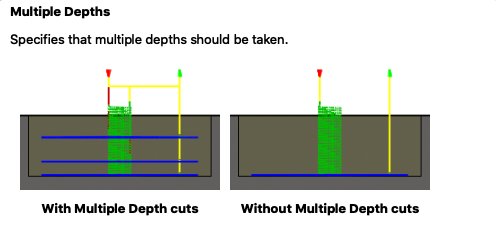
Contour toolpaths: This toolpath is great for finishing passes. You can program 2D and 3D passes. For our bottle opener, we programmed both. Click 2D > Contour, select your tooling, and input your speeds and feeds. Don’t worry about entering in stepover values for this toolpath because you’re just removing material left on the walls. But you will need to enter a stepdown. In the Passes tab, select Multiple Depths, and enter how deep you want the tool to cut for each pass. Not sure what value to enter? Pull up the speeds and feeds chart we mentioned earlier and enter the Pass Depth.
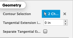
Once you’ve entered your speeds and feeds, go to the Geometry tab and select the bottom edges of your contours.
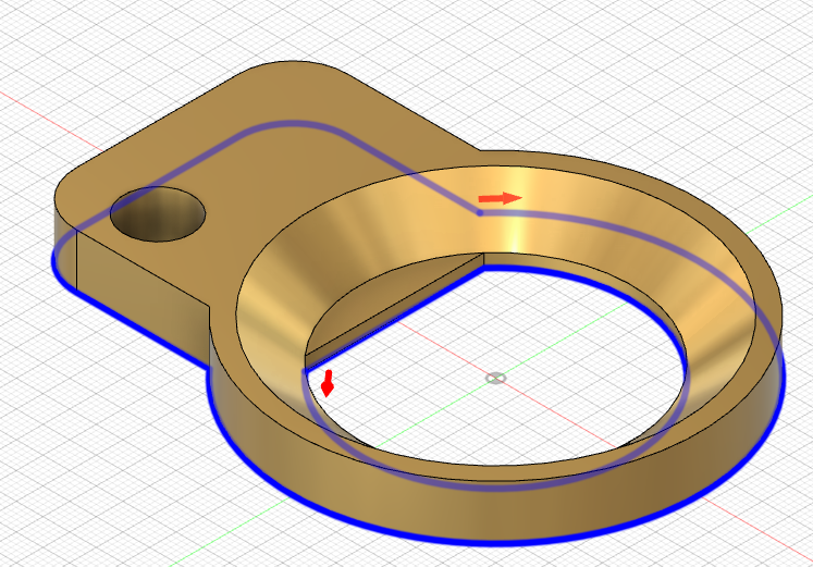
Due to the geometry of the flat end mill, the surface finish on the inner slope of our bottle opener has a stepped look rather than a smooth face. To fix this, we created a 3D contour toolpath. For this operation, we chose a smaller ball end mill to ensure we get the smooth, angled surface finish we want. To create this toolpath, click 3D > Contour, select your tooling, and enter your speeds and feeds.

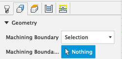
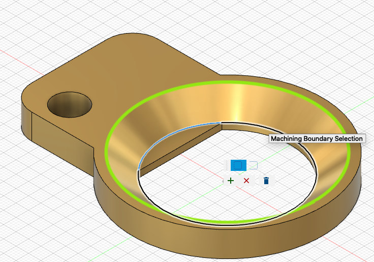
Then go to the Geometry tab and restrict your machining boundaries. We restricted our machining boundary to just the slope by selecting our two edges.
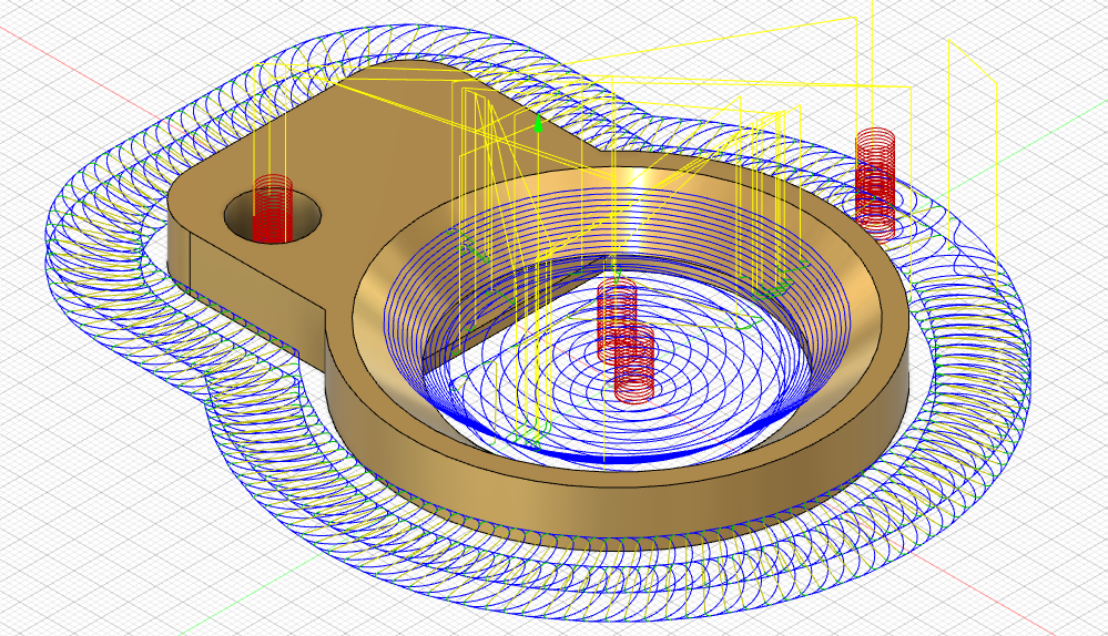
Another great thing about Fusion 360 is that you can simulate your toolpaths as you go. We love this feature because it allows us to preview our toolpaths and make sure that we’ve programmed an efficient operation. You can simulate individual toolpaths or all of them at once. To simulate an individual toolpath, right-click on the toolpath you want to preview, click Simulate, and hit the play button at the bottom of your screen. If you want to simulate all your toolpaths, click Actions > Simulate and then press play.

Once you’re satisfied with your toolpaths, generate your G-code by clicking Actions > Post Process.

A window will pop up, where you can select the CNC machine you’re using. If you’re generating G-code for the Bantam Tools Desktop PCB Milling Machine, select “Othermill (Otherplan)” for your post processor. You can name your file and add any additional comments by filling out the Program Number and Program Comment boxes, as well as the units you used.

Note: The Bantam Tools Desktop PCB Milling Machine was previously called the Othermill.
When you’re done, click OK and save the G-code file to your computer. Congrats—you just programmed your CAM and are ready to get milling!
While there are many ways you can customize your toolpaths to dial in your cutting strategies, the facing, adaptive, and contour toolpaths are a solid place to start when programming your CAM. We hope this gives you more insight into how you can use Fusion 360 with the Bantam Tools Desktop PCB Milling Machine. If you’re looking for more resources about Fusion 360, we recommend the YouTube channels of John Saunders and Lars Christensen, as well as Autodesk’s basic tutorials and our Fusion 360 support guide.
Is there a topic you’d like us to cover in our next how-to video? Email resources@bantamtools.com or reach out to us on our social channels. Be sure to follow us on Instagram, Facebook, and Twitter for the latest how-tos, CNC projects, and updates!