Six Key Steps for Designing and Milling a Topographic Map in Fusion 360
One of our favorite recent projects is the topographic map of Glacier National Park’s Hidden Lake that we milled out of aluminum 7075 on the Bantam Tools Desktop PCB Milling Machine. Topo maps show the shape of the earth’s surface, as well as other geographic features including roads, rivers, lakes, buildings, and more. The cool thing about making topo maps is that you can choose a place that means something to you!

There aren’t many guides to CNC milling topo maps available, so here we walk you through some essential steps, from selecting the topographical data to assembling the model in Fusion 360 to milling your topo map. The process will vary depending on your milling machine and desired resolution, but here are the key steps.
Step 1: Enter the coordinates of the region into Terrain2STL.

Grab your region’s coordinates from Google Maps and enter them (as shown above) on Terrain2STL. A red box will then appear around the region and you can move it as you see fit.
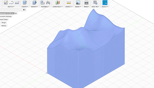
Step 2: Download the STL file and import it into Fusion 360.

Once you have your region selected in Terrain2STL, click the Download button at the bottom of the screen. Now you can import the STL file into Fusion 360. It will look similar to this:
Step 3: Convert the mesh file to a BRep file in Fusion 360.
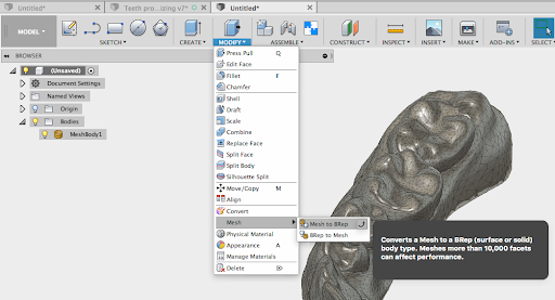
Before you can scale and slice your model to the desired size, you’ll need to convert the mesh file to a BRep file, aka a solid body. Autodesk has a great guide for converting a mesh to a BRep file. Follow the steps to convert your mesh. It’ll look something like this after you’re done:
Step 4: Scale, align, and slice.
Now that you have a solid body to work with, the next step is to update the model to the desired region of the topography you exported and reduce it to a workable size. First, you may need to scale the model. To do so, go to Modify > Scale. To maintain the highest resolution, scale it as close as possible to the finished design.

Next, create a new object with the outline and dimensions of your desired finished topo map. This is particularly helpful if you only want to mill part of the map you exported from Terrain2STL.

Then align these two bodies using the Align tool.

At this point you should have the two bodies situated one on top of the other. Use the Split Body command on the Modify panel, choosing the outer faces of the object you created as the Splitting Tool. Again, Autodesk has a detailed guide to splitting.

Using the new object as the Splitting Tool.
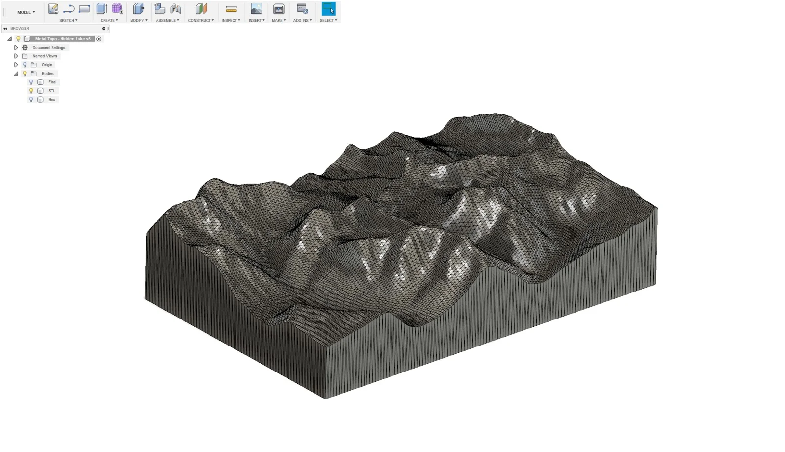
The last step is to delete the new body from the split step above. You should now have your topo map to size. It’ll look something like this:

Step 5: Rough out your topo map.
Now that your topographic model is ready to go, it’s time to mill! Head over to the Manufacture tab in Fusion 360 and begin your regular CAM workflow. While your speeds and feeds may vary—due to the material you choose and/or the CNC mill you’re using—we recommend that you use a roughing strategy first to clear away most of the material. Fusion 360’s Adaptive Clearing is a solid choice!

Step 6: Parallel pass to the finish!
Then for the fine details—and to get that smooth, sleek surface finish—hit your topo map with a parallel finishing pass using an appropriately sized ball end mill.

Here’s what our finished topo map of Hidden Lake looks like! How did yours come out?

We’d love to see what topo maps you make using the Bantam Tools Desktop PCB Milling Machine. Be sure to tag us @bantamtools and #bantamtools on your social media posts. And, as always, if you have any questions, we’re here to help at support@bantamtools.com.