How to Mill a PCB Racer with the Desktop PCB Milling Machine
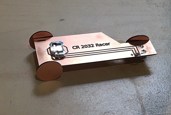
The PCB Racer is a fun and simple project to get started with the Bantam Tools Desktop PCB Milling Machine and basic electronics. It uses a pager motor to turn the drive wheel of a small race car made entirely out of double-sided FR-1 PCB material. Almost all of the parts for the car are milled with the Bantam Tools Desktop PCB Milling, including the chassis and the wheels. The remaining parts can be found at most electronics retailers.
Note: This project assumes you have basic knowledge of how to run the Bantam Tools Desktop PCB Milling Machine. If you're just getting started, check out our full library of guides.
Tools:
Computer with Bantam Tools Milling Machine Software installed
Soldering iron and solder
Wire strippers, wire cutters, and helping hands
Materials:
Note: The pager motor and motor clip that I used here are both from Solarbotics.
Pager motor
Pager motor clip
Battery, CR2032
Battery holder, CR2032
18AWG rod or wire, 3" – 4" piece
Glue, cyanoacrylate
Downloadable Files:
Step 1: Open the project file and mill the parts
The SVG files included in the .btm file were made in Inkscape, an open-source vector-graphics program. You can edit them in Illustrator or any vector-graphics software. These files are ready to open in the Bantam Tools Milling Machine Software without any editing. The thickness of the lines is optimized for a 1/32" end mill.
The four SVG files included in the project each require a different setup. By breaking the project down into separate files, we can set the engraving depth or cutout for each part. Some need to be engraved to the depth of the material, essentially cutting out the part. This is important for the parts that have a hole to drill in the center, like the wheels and the front axle brackets.
I’ve found that using double-sided tape to hold the material to the work bed adds about 0.01mm to the depth of the material. To account for this and cut all the way through the material when milling, I add 0.01mm to the custom material settings. So, if the standard double-sided FR-1 is 1.64mm:

I change that to:

This way, I can then set the engraving settings for the holes in the center of the wheels and brackets to 1.65" and ensure that I’m cutting all the way through the material.
Make sure that each file is set to the correct engraving depth in the Bantam Tools Milling Software:

When the depths are properly set, press “Cut Visible” or select each file individually. Mill away!

Step 2: Solder on the battery holder, pager motor clip, and the motor
Once you’ve cut out all the parts, now it’s time to get the electrical parts soldered on there to actually make the PCB Racer go.
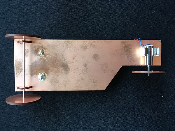
It’s helpful to have a set of helping hands to hold the PCB so you have both hands free to solder. The CR2032 battery holder can be placed through the front two holes so that the legs of the holder end up on the bottom of the PCB Racer chassis (opposite the engraving). Make sure you attach the battery holder firmly to the surface of the PCB. It’s also a good idea to add a little bead of solder on the side of the positive terminal of the battery clip to ensure a solid electrical connection.
The motor clip should be mounted on the bottom with the legs of the clip soldered to the top of the board.
Finally, solder the two wire leads from the pager motor to the end of the PCB traces you engraved out (the lines coming from the battery). The polarity of the DC power from the battery determines the direction of motor rotation. With the motor axle pointed towards the top of the PCB Racer, connect red to positive and blue to negative, and the motor will rotate clockwise, driving the racer forward.
Note: For the motor shaft, I used a small piece (1/2" or so) of wire insulation I stripped off some 22AWG wire. I placed it on the shaft, mounted the wheel, then trimmed the excess. The same process could be used for front wheels if they’re loose, and some experimentation could be needed to dial it in.
Step 3: Assemble the PCB Racer
The two brackets will probably be a tight fit. It’s a good idea to place them in to make sure they go in smoothly before gluing. Just a little dab of cyanoacrylate (crazy) glue on the edge that makes contact with the PCB should do the job.
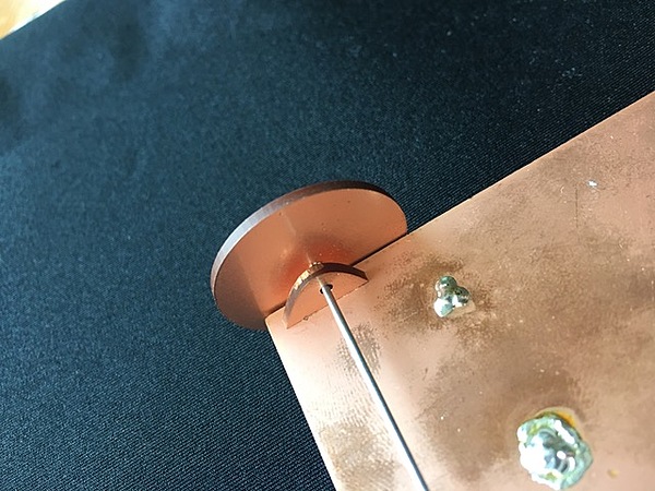
Once you have the brackets in place, cut a piece of wire to hold the wheels. I’ve found that a piece of 0.041”-diameter wire rod works well, which is roughly 18AWG. Cut it a little longer than the distance between the two brackets.
Now it’s time to add the wheels. The three wheels you cut out will all be the same size. They should fit pretty nicely into the front axle, but if not, make a bushing by stripping a piece of 18AWG wire. Same goes for the motor, where making a bushing seems to be the only way to make sure of a secure connection.
Step 4: Put in the battery and let it rip!
You’re all set! Put in a fresh CR2032 coin-cell battery and check to be sure that the motor spins the drive wheel. Currently, putting in the battery is essentially the "on" switch, while taking it out turns the racer "off." Adding a switch would be a great upgrade for V2. The racer works best on smooth floors and tabletops. I’ve found that Energizer batteries are the best for the PCB Racer. I’ve tried cheaper brands but found their low electric current doesn’t deliver enough power to get the PCB Racer very far. If you make a few of these as a class or with friends, then you can race!
